


At first I expected them to be able to communicate over USB and expose a com port, which would make programming them even easier but they don't work that way.
Micronucleus
The firmware bootloader is based on micronucleus and the USB interface is V-USB, it is a firmware/software only implementation of low-speed USB device, so any functionality you wish to implement needs to be in software, even virtual com ports, for examples you can look here.Something to note about the micronucleus firmware is the 5 seconds startup delay. If you need the device to start up immediately, you'll have to try a different approach where shorting pin 5 to ground enabled programming, otherwise it starts immediately. There is however a solution for it, but I did not test it.
So I've hooked up the Digispark, started the Arduino IDE and loaded blink and...
\micronucleus\2.0a4/launcher -cdigispark --timeout 60 -Uflash:w:Blink.ino.hex:i
Running Digispark Uploader...
Plug in device now... (will timeout in 60 seconds)
> Please plug in the device ...
> Press CTRL+C to terminate the program.
> Device is found!
connecting: 16% complete
connecting: 22% complete
connecting: 28% complete
connecting: 33% complete
> Device has firmware version 1.6
> Available space for user applications: 6012 bytes
> Suggested sleep time between sending pages: 8ms
> Whole page count: 94 page size: 64
> Erase function sleep duration: 752ms
parsing: 50% complete
> Erasing the memory ...
erasing: 55% complete
erasing: 60% complete
erasing: 65% complete
> Starting to upload ...
writing: 70% complete
writing: 75% complete
writing: 80% complete
> Starting the user app ...
running: 100% complete
>> Micronucleus done. Thank you!
no dice.
Apparently the clones were flashed with micronucleus but either an old version or wrong fuses.
So.........
Fixing Digispark Clones with USBasp
For a different purpose I've ordered a cheap USBasp 2.0 programmer from AliExpress, although it comes with a firmware already flashed, its using an old usbasp firmware so its vendor id and product id are not compatible with current avrdude which is being used by Arduino.If you insist on updating the USBasp firmware, you can follow Darell Tan post, which is based on work made by Uwe Zimmermann.
otherwise you can use PROGISP v1.72 which does a great job.
I've connected the USBasp to the Digispark


First, connect the pins according to this:
MISO <> MISO
MOSI <> MOSI
RST <> PB5
SCK <> SCK
VCC <> VCC
GND <> GND
Next, I've downloaded the lastest micronucleus firmware for ATTiny85 and flashed the bootloader:

- Select the chip as ATTiny85
- Click RD to see it is able to communicate appropriately
- Load the appropriate micronucleus firmware
- Select the fuses according to the documentation.
- Click Auto to flash the bootloader
Note: Note fuse RSTDISBL, You might not be able to use PB5 as its used as external reset pin.
We then retry to flash using Arduino IDE / USB cable and its working!
Running Digispark Uploader...
Plug in device now... (will timeout in 60 seconds)
> Please plug in the device ...
> Press CTRL+C to terminate the program.
> Device is found!
The upload process has finished.
connecting: 16% complete
connecting: 22% complete
connecting: 28% complete
connecting: 33% complete
> Device has firmware version 2.1
> Device signature: 0x1e930b
> Available space for user applications: 6522 bytes
> Suggested sleep time between sending pages: 7ms
> Whole page count: 102 page size: 64
> Erase function sleep duration: 714ms
parsing: 50% complete
> Erasing the memory ...
erasing: 55% complete
erasing: 60% complete
erasing: 65% complete
> Starting to upload ...
writing: 70% complete
writing: 75% complete
writing: 80% complete
> Starting the user app ...
running: 100% complete
>> Micronucleus done. Thank you!
ATtiny85 as a PWM generator
I've wanted a decent pwm generator that can display the duty cycle width for diagnosing problems with brushless ESCs and servo motors, so the cheap ones would not do. I've decided to build my own, as always for education and fun.We'll start with the basics, the schematics:

As mentioned previously, the ATtiny85 does not have a dedicated USB port, nor does it have a dedicated serial port, so how does it communicate over USB? It does so with V-USB, which is a software emulation for a USB port/device.
But the USB connection comes at a cost, you'll most likely encounter problems if pins 4-5 (PB3-4) will have any contact with other components. so either flash and test this chip on a breadboard or flash once and forget you did, or just don't use these pins.

So lets start with our PWM generator.
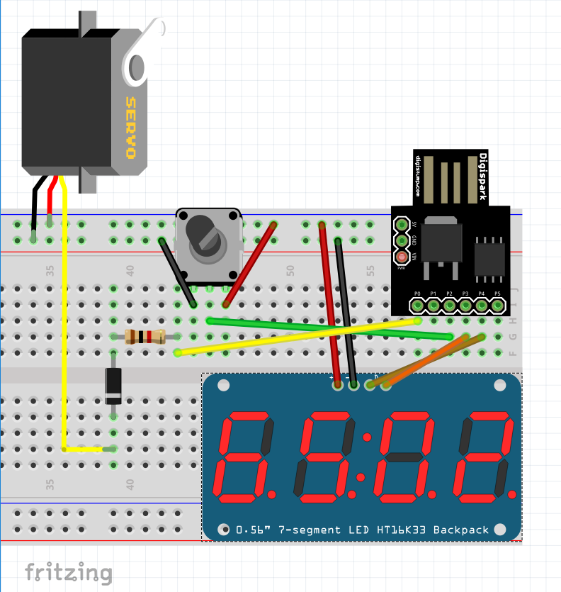
I'm using:
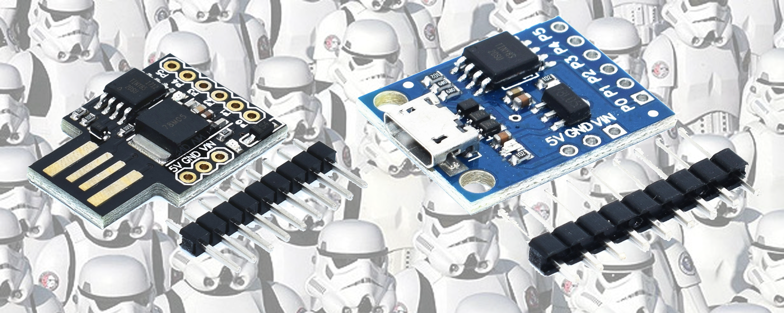
Digispark ATtiny85 Clone - This chip is good enough for this purpose, only drawback is the limited timers.
10k potentiometer - As an analog input for the 10bit ADC, which is then mapped fromo 400-2400us.
TM1637 7 segment 4 digits display - To display the selected duty cycle.
1k resistor and 1N4004 Diode - for output protection, I've just had to replace the ATtiny85 due to feedback from a servo, so its my attempt to protect it.
The source code is very simple, its actually the example from Adafruit SoftServo with display code.
Timer Limitation
The ATtiny85 has a limited timer, which can't be used to control high resolution PWM signal. but Adafruit SoftServo is a good solution for this problem, rather than use the timer to control the PWM directly, it uses the timer to call a function that simulates a PWM signal by writing the pin directly with a delayMicroseconds between.ADC Noise
At first I've tried to read the potentiometer directly and push an update to the servo, but I got so much noise from the ADC that the servo shaked a lot. I think most if not all ADCs have a noise problem. usually a capacitor and a low pass filter can eliminate some of the noise and while the ATtiny85 has a ADC Noise Reduction Mode, I've resorted to use a simple solution:long avg = 0;
for (int i = 0; i < 100; i++) {
avg += analogRead(POT_PIN);
}
val = avg / 100;
It will never be complete without a printed enclosure :-)

Further References
- I had to check which vendor/device ids to find out how to use the USBasp first as the device didn't come with any information. so I've used NirSoft's USBLogView to see which device was being plugged in/out.
- I looked into having a virtual com port with these devices, Osamu Tamura @ Recursion Co started AVR-CDC and its emulating virtual com port, but I didn't get around to test it. Two more source code libraries can be found here and here.
- Official USBasp firmware is written by Thomas Fischl
Thank you for posting. Tried to compile but produces this compile error
ReplyDelete'class Adafruit_SoftServo' has no member named 'writeMicroseconds'
Any suggestion appreciated. Thank you. Fred
One other question:
ReplyDeleteYour Fritzing diagram shows the pot connected to PB2 but your code indicates PB1:
#define SERVO_PIN PB0
#define POT_PIN PB1
#define DISPLAY_CLK PB3
#define DISPLAY_DIO PB4
Can you please clarify? Thank you.